Here is a sample configuration file (for Arduino Duemilanove):
 [Digital]
 p0=0
 P1=1
 P2=2
 P3=3
 P4=4
 P5=5
 P6=6
 P7=7
 P8=8
 P9=9
 P10=10
 P11=11
 P12=12
 P13=13
 [Settings]
 Board=Arduino Dumilanove
 vref=5
 res=1024
 AoutMax=256
 [AnIn]
 p0=0
 p1=1
 p2=2
 p3=3
 p4=4
 p5=5
 [AnOut]
 p3=3
 p5=5
 p6=6
 p9=9
 p10=10
 p11=11
As you can see, it follows syntax of ini files. The first section describes the digital pins. The first part of entries in this section is the name of the port, that will appear in the GUI controls (in the combo boxes). The second part (one after =) dictates what value will be sent to the board as part of the command frame. Similarly the analog input (AnIn) and analog output (PWM in case of Arduino) are filled up. The special section here is the "Settings" section. Here you can specify general settings such are board name, reference voltage(vref), the resolution of ADC(res) and also the maximum digital value that can be output by the DAC(/PWM) unit on the micro controller(AoutMax). The program then reads these config files and then populates the GUI controls appropriately at startup.
Using it:
Download the Arduino sketch from here.Connect the Arduino and start the download. Once downloading is done, start the GUI app by double clicking on "controller.exe" (or type in "python App.py" under linux, assuming that you have installed all the python dependencies required by this app which are pyserial and wxPython-2.8). If the Arduino is already connected, the serial port name should appear in the combo box:
 |
| Select serial port |
 |
| Select a digital pin and set a logic level |
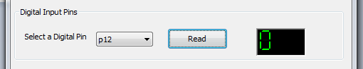 |
| Select a digital pin and read logic level |
 |
| Enter a digital value representing analog voltage and set it at pin of your choice |
 |
| Read analog voltage at selected pin |
Open the port and now you are ready to toggle GPIOs, read voltage level on GPIOs as well as read and output analog voltages.
With a different config file and matching code running on the hardware, one should be able to use any of the hardware modules available with the same GUI.
I'll soon upload code for mega(I have chipkit MAX32) which should be trival and also one more version compatible with the mbed module.
Please leave suggestions and feedbacks in the comments section below.
The project on MCU side has been modified click on this link to know more.
Note1: In case of PWM output (AnalogOut) the GUI accepts voltages in range 0-255 and not direct representation of analog voltage. These are not analog values.
Note2: The default config file here is named as conf.txt.
Note3: In case of linux, the GUI needs some tweaking so will not render properly. Will fix the issue shortly and upload the code when it is done.
There is also a compact version of this software that lets you control only the pins that you wish to use.
No comments:
Post a Comment